
Apparent velocity and angle of propeller blades: what each profile sees
The apparent angle depends on pitch and advance. Pitch, advance ratio J and slip of your propeller: propeller pitch calculator
The apparent velocity and apparent angle of a propeller blade are the velocity and direction of the fluid as each moving profile perceives it: apparent velocity combines the advance speed and the speed due to rotation, and the apparent angle changes from hub to blade tip. This is why blades are twisted. For a profile at radius r, the apparent velocity is √(Vp² + V²), where V is the advance speed and Vp the peripheral speed.
On this page:
- Apparent velocity: the cyclist example
- Apparent velocity of a blade element
- Apparent velocity and apparent angle formula
- Calculating the apparent angle along the blade
- Why blade twist compensates the apparent angle
- Induced velocity: what the profile really sees
1: Apparent velocity: the cyclist and the apparent wind
A cyclist rides at 30 km/h on a road, on a windless day. For the cyclist, the air arrives head-on at 30 km/h: this is the apparent wind. If the wind rises and blows perpendicular to the road, the cyclist feels only the sum of the two velocities, the cyclist's own and the wind's.
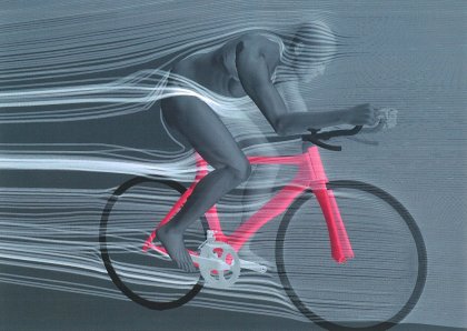
The relative air comes head-on: the cyclist's own speed sets it.
Let us measure the angle between the road and the apparent wind for a cyclist at 30 km/h:
- with a perpendicular wind of 1 km/h, the apparent wind comes almost head-on (about 2° off the road);
- with a wind of 30 km/h, it comes as much from the front as from the side: the cyclist feels it at 45° to the road;
- with a wind of 800 km/h, it comes almost from the side (about 88°). Note that with such a wind, the bike is likely to stop for good.
2: Apparent velocity of a propeller blade element
A blade element at radius r is in the same situation as the cyclist. It moves forward with the propeller at speed V and turns around the axis, which gives it a peripheral speed Vp. Its velocity relative to the fluid combines the two.
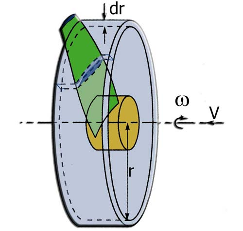
The blade element sweeps a ring of radius r and thickness dr; V is the fluid velocity along the axis, ω the rotation.
The peripheral speed grows with radius: it is therefore larger at the blade tip than near the centre. With n the rotational speed in revolutions per second:
Vp = 2π r × n
with Vp in m/s, r in m and n in rev/s.
3: Apparent velocity and apparent angle formula
The peripheral speed and the advance speed are perpendicular. The apparent velocity therefore follows from the Pythagorean theorem, and its angle from a tangent:
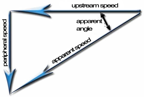
The resultant of the upstream fluid velocity and the peripheral velocity is the apparent wind. On this diagram, the angle is measured from the direction of the axis.
Vapp = √(Vp² + V²) and tan θ = Vp / V
with Vapp the apparent velocity (m/s), V the upstream fluid velocity (m/s) and θ the angle between the propeller axis and the apparent wind. The pages on twist and pitch rather measure the apparent angle φ from the plane of rotation; the two are complementary:
φ = 90° − θ = atan (V / Vp)
Near the centre, the relative velocity is mostly due to V: it is almost parallel to the axis. At the blade tip, the peripheral speed dominates and the direction moves closer to the plane of rotation.
4: Example: calculating the apparent angle along the blade
Let us take the boat from the pitch page: it moves at 3 m/s, with a propeller turning at 5 revolutions per second (300 rpm).
- At r = 0.10 m: Vp = 2π × 0.10 × 5 = 3.14 m/s, so Vapp = 4.34 m/s and φ = 43.7°.
- At r = 0.40 m: Vp = 12.57 m/s, so Vapp = 12.92 m/s and φ = 13.4°.
Between these two radii, the apparent angle drops by about 30°. This example is a hand calculation; it does not come from a particular propeller.
5: Why blade twist compensates the apparent angle
Blade elements are pieces of wing. Like a wing, they must receive the fluid at a certain angle of attack to create lift. But the apparent wind changes direction with radius. To keep the angle of attack seen by each element close to the optimum, the blade must therefore be twisted.
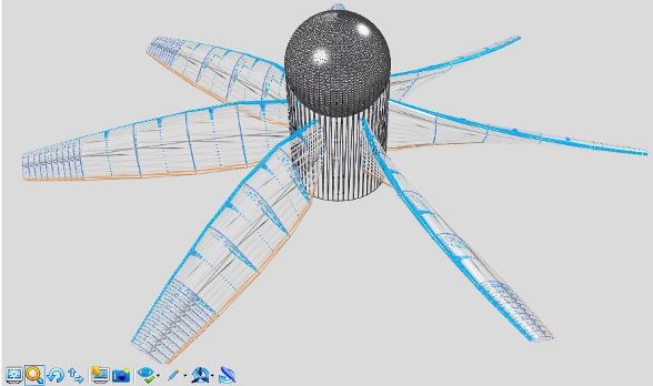
The inclination of the sections changes from hub to blade tip: this twist compensates for the variation of the apparent angle.
This variation of the apparent velocity along the radius is the reason for the twist of propeller blades.
6: Induced velocity: the velocity really seen by the profile
The velocity really seen by the profile differs slightly from the apparent velocity, because the profile itself acts on the direction and speed of the fluid:
- the air just in front of the propeller of an aircraft standing on the runway, engine running, is drawn into the propeller;
- the air just in front of the rotor of a working wind turbine is slowed down.
If we computed the apparent velocity of the standing aircraft from the rotational speed and the air speed far upstream alone, we would find no axial component. Yet just in front of the propeller, an axial airflow does exist, strong enough to be dangerous to anyone who comes close. This flow is induced by the propeller. It must be taken into account in the twist calculation to evaluate the angle of attack of the profile correctly. The page on induced velocity of a propeller details this phenomenon, and the propeller and wing calculation theories give the formulas.
Heliciel computes these velocities, induced velocities included, for each blade element, and derives the optimum twist of your propeller. The exported plans then let you build the prototype: see the presentation of the software.
To go further, we can see how blade twist and pitch angle are computed element by element, or how the operating point sets the advance speed and rotational speed each profile sees.
 Global site map
 Mecaflux
 Tutorials Mecaflux Pro3D
 Tutorials Heliciel
 Tutorials Heliciel PRO CFD
 Mecaflux Store
 Compare software functions
 Quotes, Orders, Payment Methods
 project technical studies